How to Measure Flat Face Hydraulic Couplers (ISO 16028 Quick Disconnect)
- Share
- Issue Time
- Jul 6,2026
Summary
"Size" always refers to the nominal flow passage, not the external body or thread diameter. Mismatched threads will leak even if the bodies couple together.
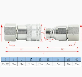
How to Measure Flat Face Hydraulic Couplers (ISO 16028 Quick Disconnect)?
Flat face hydraulic couplers—often referenced against the ISO 16028 standard—are the global workhorse for leak-free, high-flow hydraulic connections in construction, agriculture, mining, and industrial equipment. If you've ever tried to replace a coupler and discovered that "3/4 inch" printed on the side doesn't match any thread you own, you're not alone. Mis-measuring flat face couplers is one of the most common—and costly—mistakes in hydraulic maintenance. An incorrectly sized or mis-threaded coupler can restrict flow, spike pressure drop, trigger overheating, or worse, blow out under load. This guide walks global buyers, service technicians, and procurement teams through exactly how to measure an ISO 16028 flat face quick disconnect, how to decode what "size" actually means, and how to apply the STAMP method so you don't just get the dimensions right—you get the application right.
Why "3/4 Flat Face" Doesn't Mean What You Think
In hydraulic shorthand, when someone says "3/4 flat face hydraulic coupler," they are referring to the nominal internal flow path (also called DN – Diameter Nominal), not the external thread diameter, and not the hex size. A 3/4" (DN19) ISO 16028 coupler might have a 1.06" flange OD, a 1-3/16" hex, and an SAE ORFS, BSPP, or UNF thread behind it depending on regional spec and OEM preference. That's why measuring matters: size alone never guarantees compatibility. You need the flow-path size plus the thread type, sealing style, pressure rating, and materials—especially when sourcing globally where a machine built in Italy, shipped to the U.S., and serviced in Australia might carry three different thread conventions on the same skid.
What Is ISO 16028 (and Why It Matters for Measurement)
ISO 16028 is the international standard that defines dimensions, performance, and interchangeability for flat face (also called "flush face" or "planar") hydraulic quick disconnect couplings in sizes from DN6 (1/4") up through DN50 (2"). Its defining visual is the flat sealing surface that sits flush when disconnected, minimizing fluid loss and preventing air/contaminant ingress—critical for mobile hydraulics and environmentally sensitive job sites. Because ISO 16028 mandates dimensional interchangeability on the mating faces, a 3/4" ISO 16028 male from one brand should seal cleanly to a 3/4" ISO 16028 female from another. Should being the keyword—because the flange face is standardized, but the port thread that screws into your machine is not. That's the trap: two couplers can both be "3/4 ISO 16028" and still not thread together because one has -12 ORFS and the other has G3/4 BSPP. Measurement catches this before you're standing in the yard with a wrench that doesn't fit.
Tools You'll Want Before You Start
- Digital caliper (preferred) or vernier caliper – for OD, ID, hex, and flange measurements to 0.1 mm accuracy.
- Thread pitch gauge – essential for distinguishing UN/UNF, BSPP, BSPT, and metric pitch.
- Thread identification ruler or "thread check" card – handy for field techs who don't carry a full gauge set.
- Straightedge or steel rule – to confirm the face is truly flat (worn couplers can develop a slight crown).
- Marker & log sheet – record every dimension before you disconnect anything else; once fittings are loose, they get mixed up fast.
Step-by-Step: How to Measure a Flat Face Hydraulic Coupler (ISO 16028)
1. Identify the Nominal Size (Flow Path / DN)
Lay the coupler on a bench and look at any embossed marking: 1/4, 3/8, 1/2, 3/4, 1", etc. These correspond to DN6, DN10, DN12.5, DN19, DN25 under ISO 16028. If there's no marking (common on wear items), measure the internal bore at the inlet side with calipers and cross-reference to standard DN tables. Remember: this number describes flow capacity, not thread OD. A 3/4" (DN19) ISO 16028 coupler typically passes ~75–115 L/min depending on design, but the thread behind it could be anything from 1-3/16"-12 UN to G3/4 BSPP.
2. Measure the Flat Face (Flange) Outer Diameter
Close the calipers across the flat sealing face. For ISO 16028, this flange OD is standardized per DN size, which is your first sanity check: if your "3/4" coupler's flange OD isn't ~1.060" (26.9 mm), you may be looking at a non-ISO proprietary flat face or a worn part. The flange face should be smooth, scratch-free, and sit dead flat—any pitting or embedding means the coupler should be replaced regardless of measurement.
3. Measure Hex Size (Across Flats)
Measure the nut or body hex with calipers. This isn't critical for sealing, but it tells you what wrench you'll need and sometimes hints at thread family (e.g., SAE ORFS -12 uses a 1-3/16" hex; BSPP 3/4 often uses 32 mm or 1-1/4" depending on region). Log it—field mechanics will thank you.
4. Determine Thread Type and Pitch (The Dealbreaker)
Unscrew the coupler or measure the exposed threaded tail. Use the pitch gauge:
- UNF / UN (Unified National Fine/Coarse) – 1/4" increments, 12–16 TPI typical for ORFS/SAE in North America.
- BSPP (G) – parallel British Standard Pipe, 55° thread flank, common in Europe, UK, Asia-Pacific. G3/4 = 3/4" BSPP.
- BSPT (R/Rp) – tapered BSP, also 55°, seals by thread interference; common on older EU/UK equipment.
- Metric (M) – e.g., M27x2, common on continental European OEMs.
- NPT/NPTF – tapered American pipe thread; not ISO 16028-standard for the coupler face side, but you'll see NPT on the hose side of a "convertible" flat face unit.
Write down: thread diameter × pitch + family. Example: 1-3/16"-12 UNF (ORFS) or G3/4 BSPP. This is the single data point that prevents a "close enough" mismatch.
5. Measure Overall Length & Locking Mechanism
From the back of the flat face to the end of the threaded tail (for females) or to the end of the nipple (for males). Also note whether the sleeve is sleeve-retract (push to connect/disconnect) or screw-type (less common in ISO 16028 but exists for high-pressure variants). Some ISO 16028 couplers add a secondary locking collar for vibration-prone applications—measure its position if present.
6. Check Pressure Rating Markings
Most ISO 16028 couplers are stamped with WP (working pressure) and sometimes BP (burst pressure) in bar or psi. Typical DN19 (3/4) ISO 16028 rated ~350–420 bar WP / ~1000+ bar BP depending on brand and material. If the stamp is gone, you'll need to cross-reference the brand/model or—safer—replace rather than guess on high-pressure circuits.
Common Port Thread Types on ISO 16028 Couplers (Global Cheat Sheet)
Because ISO 16028 only standardizes the mating face, the port thread behind it follows regional/OEM preference. Here's what you'll encounter most:
- SAE ORFS (O-Ring Face Seal, UNF thread) – North American mobile hydraulics default. Excellent vibration resistance; the O-ring lives in the female socket, not the coupler, so the flat face does the primary sealing.
- BSPP (G parallel, 55°) – European, Australian, and Asian equipment. Seals via bonded seal washer or O-ring on the shoulder, not thread interference.
- Metric (DIN 2353 / M-thread) – German and Scandinavian OEMs; often paired with 24° cone seat or O-ring.
- NPTF (tapered) – U.S. industrial legacy; seals by thread dope + taper interference. Not ideal with flat face (thread taper can misalign the flange if over-tightened), but common on the hose-side adapter.
Beyond Size: The STAMP Method for Flat Face Selection
Measuring gets you the dimensions. STAMP gets you the right coupler for the job. It's a five-criteria framework used across the hydraulic industry (popularized by Ehhydraulic and others) that prevents the "size is right but everything else is wrong" scenario:
- S – Size (Nominal flow path / DN): Match the internal bore to your required flow. Undersize = pressure drop & overheating. Oversize = unnecessary cost and possibly longer overall length that fouls nearby structure.
- T – Thread / Type: Port thread family (ORFS, BSPP, Metric, NPTF) and connection type (male nipple vs. female body, straight vs. 45°/90° elbow). Also note if you need a dust cap/plug—flat face couplers are often sold as sets.
- A – Application: What machine? Skid steer, excavator, tractor, press, forestry? Duty cycle, impulse loading, vibration, ambient temperature, and whether the circuit sees frequent connect/disconnect all change the coupler choice. Construction sites favor heavy-duty sleeve designs; ag equipment favors easy one-hand connect.
- M – Media / Material: Standard nitrile (NBR) seals cover mineral oil; HFC/HFD fire-resistant fluids need EPDM or FKM. Coupler body material: carbon steel (most common), stainless (marine/food/pharma), zinc-nickel plating for salt-spray environments. Also check seal compatibility with any biodiesel or synthetic oils in your region.
- P – Pressure (+ Temperature): Working pressure, burst pressure, and temperature range. ISO 16028 DN19 typically rated ~350–420 bar WP, but verify per SKU. If your system sees pressure spikes > WP even briefly, step up a size or a pressure class. Don't forget temp: standard NBR seals tap out around 100°C; FKM goes higher.
Pressure Drop: The Invisible Reason to Measure Carefully
Even a correctly sized ISO 16028 coupler adds restriction. Pressure drop across a quick disconnect comes from three sources: (1) the reduction into the nominal bore, (2) the valve poppet inside the coupler, and (3) any flow turbulence at the mating interface. Undersizing a coupler to "save money" on a 3/4 circuit can add 2–5 bar of constant drop—multiply that by 8-hour duty cycles and you're burning fuel and generating heat the cooler has to dump. Use the coupler manufacturer's ΔP curve (flow vs. pressure drop) to sanity-check: a DN19 at 100 L/min should typically show <2 bar drop on a good ISO 16028 design. If your curve is steeper, step up to DN25 or check for internal debris/restriction.
ISO 16028 Flat Face Coupler Size Reference (Common Global Sizes)
| Nominal (inch) | DN | Typical Flange OD | Typical Flow Range | Common Applications |
|---|---|---|---|---|
| 1/4" | DN6 | ~0.590" (15 mm) | up to ~15 L/min | Pilot lines, small aux circuits, compact ag |
| 3/8" | DN10 | ~0.787" (20 mm) | ~15–35 L/min | Compact tractors, mini-excavator aux |
| 1/2" | DN12.5 | ~0.945" (24 mm) | ~35–60 L/min | Mid-size skid steers, telehandlers |
| 3/4" | DN19 | ~1.060" (26.9 mm) | ~60–115 L/min | Skid steers, excavators, loaders, ag implements (the global "sweet spot") |
| 1" | DN25 | ~1.260" (32 mm) | ~115–190 L/min | Large excavators, mining, high-flow attachments |
| 1-1/4" & up | DN32–DN50 | 1.575"–2.362" (40–60 mm) | 190 L/min+ | Heavy mining, marine, industrial presses |
Quick Field Checklist Before You Order (Global Procurement Version)
- ☐ Nominal size / DN confirmed (caliper the bore if unmarked)
- ☐ Flange OD matches ISO 16028 table for that DN
- ☐ Thread family + pitch identified (ORFS? BSPP? Metric? NPTF?)
- ☐ Hex size logged for wrench planning
- ☐ Male vs. Female, Straight vs. Elbow confirmed
- ☐ WP/BP legible (or cross-referenced to model)
- ☐ Seal material matched to fluid (NBR/FKM/EPDM)
- ☐ Dust caps/plugs included? (flat face lives or dies by contamination control)
- ☐ Interchange brand check: ISO 16028 face is universal, but internal valve & sleeve feel can vary—if mixing brands on a fleet, test one first
Conclusion: Measure Once, Connect Every Time
A flat face hydraulic coupler looks simple—two metal halves, a sleeve, an O-ring. But behind that flush face sits a stack of standards, thread conventions, pressure classes, and material choices that differ from Ohio to Osaka. Measuring a flat face coupler for ISO 16028 interchangeability isn't just about grabbing calipers; it's about capturing the six data points (DN, flange OD, hex, thread spec, length, pressure) and then running them through STAMP so the coupler survives the application, not just the shelf. For global fleets, the payback is tangible: fewer emergency shipments, less downtime, no "it almost fit" stories. When in doubt—and especially when mixing brands across regions—send the measurements and a photo to a hydraulic specialist rather than guessing. Your system pressure (and your mechanic's knuckles) will thank you.
Need help identifying a flat face coupler on your machine? Ehhydraulic's technical team works with global OEMs and service networks daily—send your measurements and photos, and we'll confirm the ISO 16028 match, thread conversion, and pressure class so you order once and get back to work. Contact Ehhydraulic →