How to identify NPT thread and other hydraulic fitting types?
- Share
- Issue Time
- Jul 9,2025
Summary
Learn how to identify the various types of quick coupler fittings and hydraulic threads including the most common NPT thread and others such as SAE, BSPP, JIC, ORFS and others.
How to Identify NPT Thread and Other Hydraulic Fitting Types
This article will go through the steps of how to identify hydraulic coupler or adapter fitting thread sizes to help you determine the correct size thread you need for your application.
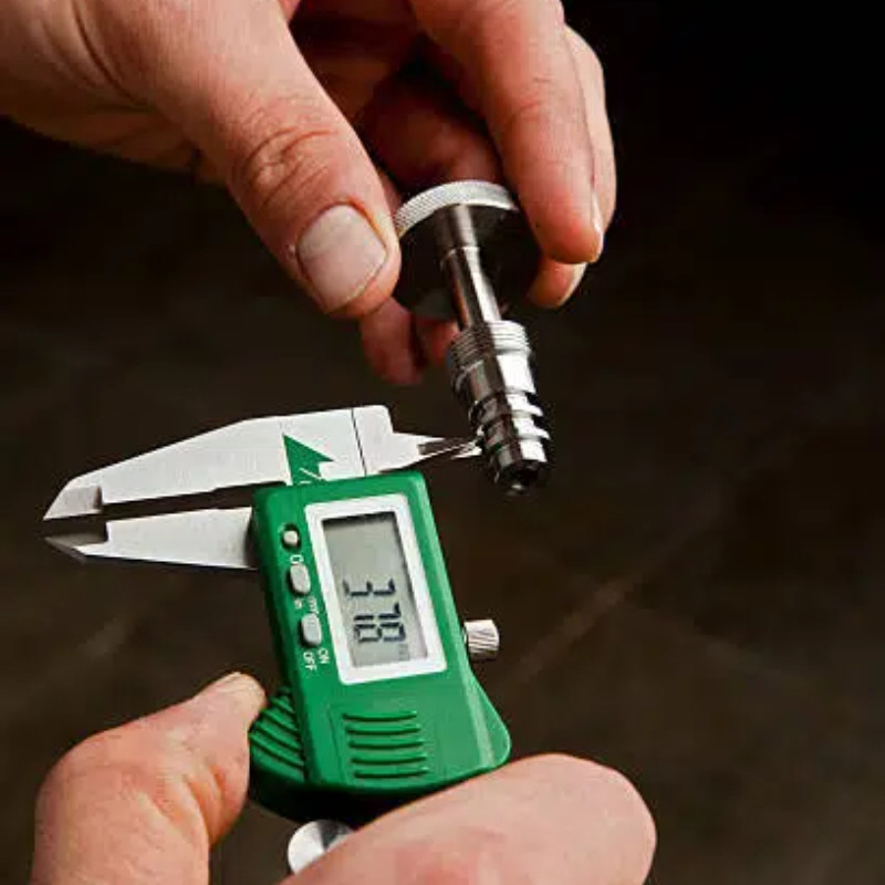
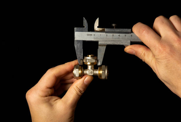
Measure the diameter of the thread
To determine thread sizes, first measure the diameter with a caliper. For external (male) threads, use the lower jaws; for internal (female) threads, use the upper jaws.
Record these measurements to compare with selection charts. Note that your reading may not exactly match the chart due to manufacturing tolerances or wear, but the difference is usually minor—just pick the closest size.
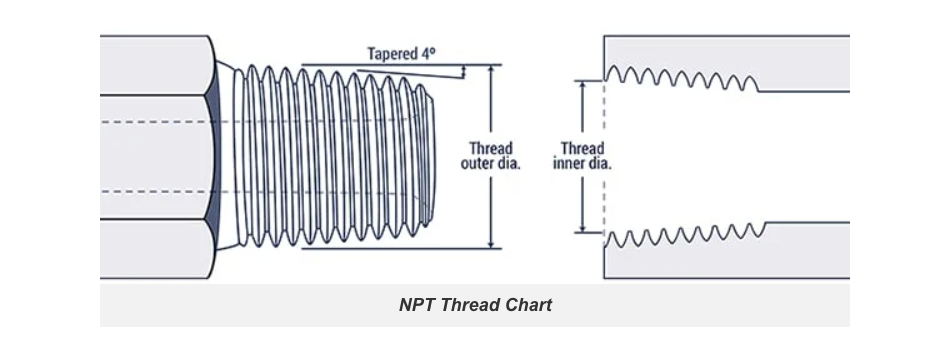
National Pipe Thread (NPT):
This thread type can be identified by its unique tapered 4° features: a reverse tapered 4° seat in the female half and a 4° internal chamfer in the male half.
| Inch size | Dash size | Threads per Inch | Male Thread O.D. (in) | Female Thread I.D (in) |
| 1/8'' | ‒2 | 27 | 13/32 | 3/8 |
| 1/4'' | ‒4 | 18 | 17/32 | 1/2 |
| 3/8'' | ‒6 | 18 | 11/16 | 5/8 |
1/2'' | ‒8 | 14 | 27/32 | 25/32 |
3/4'' | ‒12 | 14 | 1 1/16 | 1 |
1'' | ‒16 | 11.5 | 1 5/16 | 1 1/4 |
1-1/4'' | ‒20 | 11.5 | 1 21/32 | 1 19/32 |
1-1/2'' | ‒24 | 11.5 | 1 29/32 | 1 13/16 |
2'' | ‒32 | 11.5 | 2 3/8 | 2 5/16 |
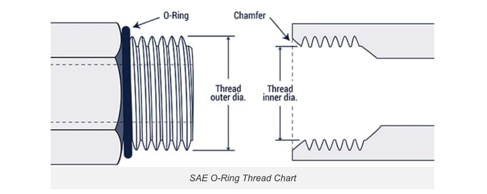
SAE Straight Thread O-Ring (ORB):
These are SAE J1926-1 and ISO 11296-1 threads (also compliant with MS16142), using UN/UNF standards for medium-to-high-pressure hydraulic systems. Key identifiers include:
-An O-ring on the male thread
-A small chamfer on the female thread to seat the O-ring
| Inch size | Dash size | Thread Size | Male Thread O.D. (in) | Female Thread I.D (in) |
| 1/8'' | ‒2 | 5/16 – 24 | 5/16 | 9/32 |
| 3/16'' | ‒3 | 3/8 – 24 | 3/8 | 11/32 |
| 1/4'' | ‒4 | 7/16 – 20 | 7/16 | 13/32 |
5/16'' | ‒5 | 1/2 – 20 | 1/2 | 15/32 |
3/8'' | ‒6 | 9/16 – 18 | 9/16 | 17/32 |
1/2'' | ‒8 | 3/4 – 16 | 3/4 | 11/16 |
5/8'' | ‒10 | 7/8 – 14 | 7/8 | 13/16 |
3/4'' | ‒12 | 1 1/16 – 12 | 1 1/16 | 1 |
7/8'' | ‒14 | 1 3/16 – 12 | 1 3/16 | 1 1/8 |
1'' | ‒16 | 1 5/16 – 12 | 1 5/16 | 1 1/4 |
1-1/4'' | ‒20 | 1 5/8 – 12 | 1 5/8 | 1 9/16 |
1-1/2'' | ‒24 | 1 7/8 – 12 | 1 7/8 | 1 13/16 |
2'' | ‒32 | 2 1/2 – 12 | 2 1/2 | 2 7/16 |
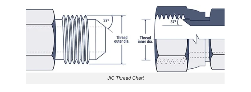
JIC 37° Flare or SAE J514:
This thread style is widely used in fluid power systems. Its key identifying feature is a 37° flared seat on both the male and female components.
Inch Size | Dash Size | Thread Size | Male Thread O.D. (in) | Female Thread I.D. (inch) |
| 1/8'' | ‒2 | 5/16 – 24 | 5/16 | 9/32 |
| 3/16'' | ‒3 | 3/8 – 24 | 3/8 | 11/32 |
| 1/4'' | ‒4 | 7/16 – 20 | 7/16 | 13/32 |
5/16'' | ‒5 | 1/2 – 20 | 1/2 | 15/32 |
3/8'' | ‒6 | 9/16 – 18 | 9/16 | 17/32 |
1/2'' | ‒8 | 3/4 – 16 | 3/4 | 11/16 |
5/8'' | ‒10 | 7/8 – 14 | 7/8 | 13/16 |
3/4'' | ‒12 | 1 1/16 – 12 | 1 1/16 | 1 |
7/8'' | ‒14 | 1 3/16 – 12 | 1 3/16 | 1 1/8 |
1'' | ‒16 | 1 5/16 – 12 | 1 5/16 | 1 1/4 |
1-1/4'' | ‒20 | 1 5/8 – 12 | 1 5/8 | 1 9/16 |
1-1/2'' | ‒24 | 1 7/8 – 12 | 1 7/8 | 1 13/16 |
2'' | ‒32 | 2 1/2 – 12 | 2 1/2 | 2 7/16 |
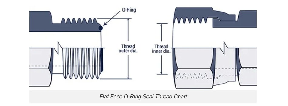
O-Ring Face Seal (ORFS) or SAE J1453:
This design features:
-A male connector with a face-mounted O-ring
-A female connector with a machined flat sealing surface
| Inch size | Dash size | Thread Size | Male Thread O.D. (in) | Female Thread I.D. (in) |
| 1/4'' | ‒4 | 9/16 – 18 | 9/16 | 17/32 |
3/8'' | ‒6 | 11/16 – 16 | 11/16 | 5/8 |
1/2'' | ‒8 | 13/16 – 16 | 13/16 | 3/4 |
5/8'' | ‒10 | 1 – 14 | 1 | 15/16 |
3/4'' | ‒12 | 1 3/16 – 12 | 1 3/16 | 1 1/8 |
1'' | ‒16 | 1 7/16 – 12 | 1 7/16 | 1 3/4 |
1-1/4'' | ‒20 | 1 11/16 – 12 | 1 11/16 | 1 5/8 |
1-1/2'' | ‒24 | 2 – 12 | 2 | 1 15/16 |
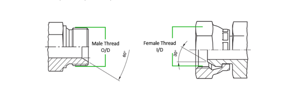
British Standard Pipe (BSP):
BSP (Whitworth) threads feature two sealing methods:
-Metal-to-metal contact at 60°
-Hybrid metal/O-ring designs
Two main types exist:
-BSPP (parallel) - Constant diameter
-BSPT (tapered) - Diameter decreases along the thread
Identification requires measuring:
-Outside diameter
-Thread pitch (count per 25.4mm)
| Dash Size | Size (inches) | TPI | Male O/D (mm) | Female I/D (mm) | Hex |
| ‒2 | 1/8'' | 28 | 9.7 | 8.9 | 14 |
| ‒4 | 1/4'' | 19 | 13.2 | 11.9 | 19 |
| ‒6 | 3/8'' | 19 | 16.5 | 15.2 | 22 |
‒8 | 1/2'' | 14 | 20.8 | 19.1 | 27 |
‒10 | 5/8'' | 14 | 22.4 | 20.3 | 30 |
‒12 | 3/4'' | 14 | 26.4 | 24.6 | 32 |
‒16 | 1'' | 11 | 33.0 | 31.0 | 41 |
‒20 | 1-1/4'' | 11 | 41.9 | 39.6 | 50 |
‒24 | 1-1/2'' | 11 | 47.8 | 45.5 | 55 |
‒32 | 2'' | 11 | 59.7 | 57.4 | 70 |
Final considerations
The selection charts include reference numbers like dash sizes and nominal dimensions. If you know your fitting style and one of these values, you can quickly identify the correct part. Remember, these are just naming conventions - when in doubt, always verify using the measurement methods described earlier.