What is a quick disconnect coupling and how does it work?
- Share
- Issue Time
- Oct 19,2026
Summary
A quick disconnect coupling (QDC) is a self-sealing fitting that connects or separates fluid or air lines by hand — no tools, no spills. A spring-loaded valve in each half seals automatically on disconnect, then opens once the halves lock together.
Fluid Power Guide | 7 min read | For global OEMs, distributors and equipment owners
What is a quick disconnect coupling and how does it work?
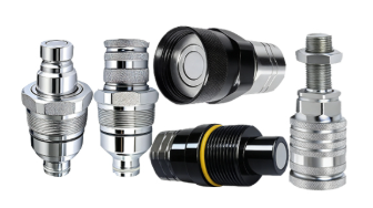
A quick disconnect coupling (also called a QD coupling, quick coupler or quick release coupling) is a two-part mechanical device that lets an operator connect and disconnect a fluid line in seconds, by hand, without tools and without draining the circuit. It consists of a male half (plug or nipple) and a female half (coupler or socket), each holding a spring-loaded valve. When the halves are apart, both valves stay closed and the fluid is sealed in. When the male half is pushed into the female half, a spring-loaded sleeve drives a ring of locking balls into a machined groove, the joint locks, and the two valve elements unseat and open, creating a sealed flow path that carries the working pressure of the circuit. Pulling the sleeve back reverses the sequence: the valves close first, then the halves separate, so the only fluid released is the small trapped volume between the sealing faces.
That principle lets a tractor operator swap from a front loader to a baler in under a minute, or a crew change an excavator bucket without bleeding the hydraulics. It also means the coupling sits directly in the pressure path, deciding how much fluid is lost per connection, how much pressure is dropped across the joint, and how safely the joint resists pull-apart forces.
Key takeaways
- Two halves — male plug and female coupler — each with its own shut-off valve.
- Connection is tool-free: a spring-loaded sleeve and locking balls hold the joint against internal pressure.
- Valves open only after the seal is made and close before separation, which is why spillage is minimal.
- Material follows the fluid: carbon steel for general hydraulics, stainless steel for corrosion, brass for refrigeration and mould and die.
- Seal compound drives temperature and chemical compatibility: NBR standard, FKM (Viton) for a wider range.
What is a quick disconnect coupling?
A quick disconnect coupling is a precision-engineered fluid connector built to be mated and unmated repeatedly, at working pressure, by one person, with no spanners and no system bleeding. A threaded hydraulic fitting must be tightened to a torque value and opens the line completely when loosened; a QD coupling keeps both sides of the circuit sealed at every moment. That single difference turns an attachment change from a twenty-minute maintenance job into a ten-second hand movement.
The same concept serves hydraulic oil on mobile machinery, compressed air in plants, water and glycol in cooling circuits, refrigerants in air conditioning service, fuels and chemicals in transfer lines, and gases in medical installations. Because pressure, fluid and environment change from one application to the next, couplings are engineered in families defined by an interchange profile, a size, a pressure rating and a seal material.
How does a quick disconnect coupling work?
The principle is simple, but the sequence is what makes it safe. Two spring-loaded valves face each other, and the mechanical lock that holds the coupling together is the same mechanism that opens the flow path. Nothing opens until the joint is sealed.
- Alignment and insertion. The operator retracts the sleeve on the female half, aligns the male nipple and pushes it in, so the nose of the plug contacts the poppet or flat-face valve of the socket.
- Mechanical locking. As the plug seats, its groove passes under a ring of locking balls and the spring-loaded sleeve snaps forward, driving the balls into that groove. The joint is now locked and resists the axial force generated by internal pressure.
- Valve opening and sealing. With the lock engaged, the two valve elements push each other off their seats while the body seal — usually an elastomer O-ring with a back-up ring — compresses against the mating surface. Fluid flows, with a pressure drop set by the internal geometry.
- Disconnection. Pulling the sleeve back re-seats the valves and stops flow before the halves separate. The residual volume between the faces is the main difference between coupling families, and the reason flat-face designs are specified where spillage must be almost zero.
Because lock and valve are coupled, a QD coupling cannot be half connected: it is either locked and flowing, or unlocked and sealed on both sides. That is why these couplings are trusted on circuits running at several hundred bar.
Working pressure, residual pressure and connect-under-pressure
Three pressure conditions define real behaviour. Working pressure is the maximum continuous rating; burst pressure is the failure point, normally several times higher, giving the safety margin hydraulic circuits require. Residual pressure is trapped pressure in a hose after shutdown, from thermal expansion of the oil or from a load hanging on an actuator. A standard poppet coupling can be very hard to connect by hand against it, because that pressure holds the poppet shut. Where the condition is routine, engineers specify a screw-to-connect coupling, whose threaded union forces the valve open mechanically.
Engineering note: published pressure ratings refer to the coupled pair tested as a unit. They are not transferable between brands or profiles, and pressurising a coupling beyond its rated working pressure — even during a test — risks sudden separation of the halves.
The main components of a QD coupling
- Male half (plug / nipple). The insert half, normally mounted on the implement or hose end; it carries the locking groove and the valve nose, and is the part protected by a dust cap when disconnected.
- Female half (coupler / socket). The receiving half, normally on the machine side; it houses the sleeve, locking balls, valve and main seal.
- Locking mechanism. A spring-loaded sleeve plus hardened steel balls in most hydraulic designs; a threaded union for screw-to-connect; a cam or bayonet in some pneumatic designs.
- Valve. Poppet valves are the general-purpose solution. Flat-face valves present a smooth, wipe-clean surface and admit almost no air or dirt, which is why they are the modern standard on construction attachments. Ball and diaphragm valves appear in specific pneumatic and chemical designs.
- Seals. NBR (nitrile) is the standard compound for mineral oil. FKM (Viton) broadens the temperature range and chemical resistance. EPDM, HNBR, PTFE and polyurethane serve water-glycol, phosphate esters, refrigerants and hot water.
- Back-up rings. Usually PTFE, they stop the elastomer extruding into the clearance gap during pressure spikes, so a compact coupling survives peaks above its nominal rating.
- Dust caps and plugs. A low-cost accessory with a large effect on service life: they keep abrasive dust off the sealing faces and contain the residual oil film in transport.
Common types of quick disconnect couplings
- ISO 7241-1 Series B poppet couplings. The most widely used general-purpose profile worldwide: robust, tolerant of dirt, suited to agriculture and industry.
- ISO 7241-1 Series A poppet couplings. Common on agricultural tractors and North American equipment; standardised so halves from different makers mate with each other.
- ISO 16028 flat-face couplings. The reference for construction equipment. The flush faces wipe clean in one motion, keep spillage extremely low and keep air out of the circuit, protecting pumps and valves downstream.
- Screw-to-connect couplings. For circuits with high residual pressure or strong impulses — breakers, demolition tools, long hoses left in the sun.
- Multi-couplings and modular plates. Several lines coupled in one movement, cutting connection time and operator error on multi-service attachments.
- Dry-break and breakaway couplings. Near-zero spill and automatic safe separation if a hose is pulled away under load; standard in chemical transfer, fuel handling, marine loading and aviation fuelling.
- Pneumatic and industrial interchange couplings. Lightweight bodies for compressed air, water and low-pressure services, where flow and ergonomics matter more than pressure rating.
Materials: carbon steel, stainless steel and brass
The fluid involved determines the body material, and the environment determines the surface treatment. Getting this wrong is the fastest route to premature failure, because corrosion attacks the sealing surfaces and the locking mechanism first.
- Carbon steel. The most commonly used material: extremely tough, resistant to pressure and to the tear and wear of daily use, and economical at scale. Bodies are protected with zinc or zinc-nickel plating. Sealed with NBR as standard, or with FKM (Viton) where a broader temperature range and wider fluid compatibility are needed.
- Stainless steel. Specified when high corrosion resistance is required. It offers excellent resilience and is the natural choice for corrosive fluids, marine and offshore environments, chemical and food processing, and frequently washed-down machinery. With FKM seals it also gains a wider working temperature range and becomes suitable for tougher duties.
- Brass. Resistant to corrosion, durable, strong and highly robust in service. With FKM seals it endures high temperatures, which makes it the standard answer for refrigeration systems, air conditioning and other refrigerant circuits, the mould and die industry, and snubbing units for well control.
| Material | Why it is chosen | Typical applications | Usual seal |
|---|---|---|---|
| Carbon steel | Toughness, pressure capability, wear resistance, cost efficiency | Agricultural tractors and harvesters, construction machinery, industrial stationary equipment | NBR (FKM optional) |
| Stainless steel | Corrosion resistance in harsh or wash-down environments | Marine, offshore, chemical, food processing, corrosive fluids | FKM (Viton) |
| Brass | Corrosion resistance plus high-temperature stability | Refrigeration, air conditioning, mould and die, well-control snubbing units | FKM (Viton) |
Where quick disconnect couplings are used
Quick disconnect couplings cover an unusually wide spectrum, from standard circuits to very specific ones, on machines of a few kilowatts and on stationary plant running continuously.
- Agriculture. Tractors, harvesters, front loaders, presses and seeders swap hydraulically driven implements several times a day, often in the field, in dust and mud.
- Construction and earthmoving. Compact wheel loaders, crawler cranes, excavators and skid steer loaders change buckets, breakers, grapples and augers safely and cleanly.
- Industrial stationary equipment and tools. Test benches, rolling mills, presses, injection moulding machines and power units connect instruments, jigs and interchangeable tooling.
- Refrigeration, air conditioning, mould and die, and well control. Brass couplings with FKM seals serve refrigerant and temperature-control lines, while snubbing units use couplings engineered for pressure and controlled disconnection.
Across all these sectors, reputable manufacturers design to international standards, which is what allows a coupling bought in one country to mate with a half fitted on a machine built in another — and why a global manufacturer can standardise one coupling family across its entire range.
How to choose the right quick disconnect coupling
- Define the fluid first. Mineral oil, water-glycol, phosphate ester, refrigerant, air or chemicals each demand a different body material and seal compound.
- Size the pressure. Check working and burst pressure against the real maximum, including spikes and water hammer, and confirm whether the coupling must connect under residual pressure.
- Check the flow. Flow rate and acceptable pressure drop decide the body size; an undersized coupling becomes a permanent restriction that heats the oil and slows the actuator.
- Confirm the temperature window. Ambient, fluid and external heat must all sit inside the range of body material and seal compound.
- Fix the interchange profile. Use the profile already on the machine or mandated by the segment and keep both halves in the same family; mixing profiles causes leaks and couplings that look locked but are not fully seated.
- Match threads and size. Ports run from small fractional sizes to large industrial bores with BSPP, BSPT, NPT/NPTF, metric and SAE/JIC forms, and sealing differs between tapered and parallel threads.
- Evaluate the environment. Salt spray, wash-down, dust, vibration and hose side loads shorten life and point to stainless steel, protective caps and strain-relief routing.
Installation, maintenance and failure prevention
Most coupling failures come from contamination and mechanical abuse rather than manufacturing defects. A short list of practices prevents the majority of them.
- Keep the circuit clean. Wipe both faces before connecting and refit dust caps when the halves are apart; grit on a sealing face scores it permanently.
- Torque the port correctly. Overtightening a tapered thread can crack the body; undertightening leaks at the port rather than at the valve.
- Avoid side loads. A coupling carries pressure along its axis, not bending moments; support long hoses so weight and vibration are not carried by the joint.
- Inspect seals and locking balls. Flattened O-rings, a sleeve that no longer springs back, or balls that no longer seat mean the coupling should be rebuilt or replaced.
- Never disconnect under pressure. Release residual pressure first: disconnecting a loaded line is both a spill risk and a safety risk.
- Do not mix brands or profiles blindly. Dimensions can look identical while tolerances and ratings differ, voiding the rating of the pair.
Frequently asked questions
-
What is the difference between a quick disconnect coupling and a quick coupler?
Nothing functional — both describe the same two-part device. "Quick disconnect coupling" and "QD coupling" dominate technical and North American usage; "quick coupler" and "quick release coupling" are common in European and distributor language.
-
Can a quick disconnect coupling be connected while the line is under pressure?
Standard poppet couplings are meant to be connected with the circuit depressurised. Where trapped pressure is unavoidable, specify a screw-to-connect coupling or a model rated for connection under residual pressure.
-
Why does my coupling leak after disconnection?
Usually a worn valve seal, contamination on the faces, a plug not fully seated in the locking groove, or use beyond the rated pressure or temperature. Flat-face designs plus disciplined use of dust caps eliminate most cases.
-
Are quick disconnect couplings interchangeable between manufacturers?
Only within the same dimensional standard: series A with series A, series B with series B, ISO 16028 flat-face with the same profile. Cross-mating different profiles is unsafe and invalidates the pressure rating.
The bottom line
A quick disconnect coupling is a small component with a disproportionate effect on productivity, cleanliness and safety. It seals the circuit on both sides when apart, resists internal pressure and pull-apart forces through a positive mechanical lock, and opens the flow path only once the joint is secure. Specified correctly — right profile, size, material and seal — it makes attachment changes fast and clean; specified carelessly, it becomes a leak point, a pressure drop and a source of downtime.
Need help specifying the right coupling?
Share your fluid, working pressure, flow rate, port thread and operating environment, and our technical team will recommend the profile, material and seal combination that fits your machine and your market.
Request a tailored coupling solution