Why Hydraulic Couplers Are Hard to Connect
- Share
- Issue Time
- Nov 3,2026
Summary
Hydraulic couplers are hard to connect for one reason most of the time: pressure or resistance somewhere between the two halves. Find which of the four below applies, and the fix usually takes seconds.
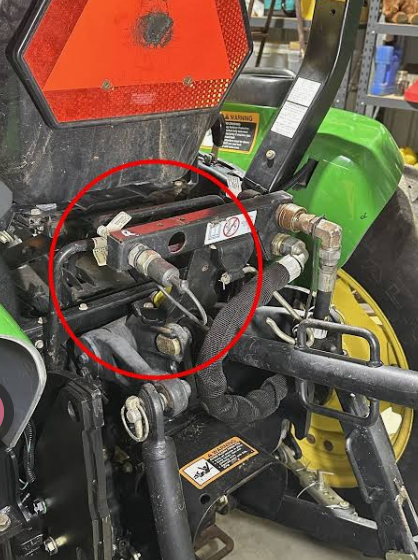
Why Hydraulic Couplers Are Hard to Connect? A global, field-focused guide to trapped pressure, thermal expansion, contamination, and the Connection Under Pressure (CUP) solutions that make quick couplings quick again. When a hydraulic quick coupling refuses to seat, the coupling is rarely defective. In most field cases, residual pressure trapped in the disconnected implement circuit holds the internal valve shut. Every common connection system — sleeve retraction, push-to-connect, screw-to-connect and lever-operated multi-couplings — shares one weakness: without a dedicated pressure-relief mechanism, the force needed to connect rises with pressure until, beyond a threshold set by the series and nominal size, the manoeuvre becomes practically impossible. Two everyday events create that pressure: a missed release before disconnection, and a slow build-up from rising ambient temperature. Hoses are rigid by design to withstand high and ultra-high pressures, so trapped fluid cannot expand its volume and thermal expansion becomes pressure. A second recurrent cause is external debris stuck to the mating surfaces. Power units have relief systems, usually actuated by a joystick on the distributor; implements generally do not, so the struggle occurs on the attachment side. Forcing the valve, striking the nipple or loosening the hose-to-coupling union to bleed oil is strongly discouraged: it damages seals, shortens life and endangers people nearby. The engineered answer is correct pressure relief, or a coupling with an integrated, often fully automatic, Connection Under Pressure (CUP) system matched to the pressure expected before connecting and disconnecting. Residual pressure is oil locked between two closed valve faces — a line isolated before the release step, a load held by a check valve, or oil warming after shutdown. A well-sealed circuit can hold pressure for days, so an attachment parked overnight may still be pressurised at dawn. Hydraulic oil expands as it warms and is nearly incompressible. In a reservoir-connected line the expansion is harmless; in a hose sealed at both ends it appears as a pressure rise, because stiff hose walls and entrained air absorb only part of it. A cool-morning connection can therefore feel solid by mid-afternoon in direct sun, in any climate with a large day/night swing. Power units always carry pressure relief, most often worked through a joystick on a hydraulic distributor. Implements usually have no equivalent path, so residual pressure prevents their valve from moving back to open the circuit. If a coupling connects cold but not hot, or frees up after a safe bleed-down, diagnose the pressure state before condemning the part. Connection opens both internal valves — a poppet or a flush-face valve — while the sleeve retracts and the locking balls engage. Pressure behind one valve pushes it closed, so the sleeve cannot complete its travel and the latch cannot release. The resistance is simple physics: F = P × A. Even modest residual pressure over a valve face of a few square centimetres generates a force on the order of hundreds of newtons, beyond comfortable hand effort. Flat-face designs expose a wider area than a pointed poppet seat, so the same pressure resists more. Oil is nearly incompressible: pushing harder cannot compress it away. There is no single pressure at which connection fails. Valve geometry, sealing area, spring preload, mechanical advantage, series and size all shift the limit. Screw-to-connect designs gain axial force from torque, which suits high-pressure duty, but the physics is unchanged. A recurrent cause is dirt on external surfaces — dust, mud, sand, dried oily grit, metal chips, crystallised residue. It jams the sleeve-to-body sliding interface ("sleeve sticking"), stops the nipple seating, and is pushed into the circuit where it scores seals and wears pumps, spools and cylinders. Flat-face profiles wipe clean far more easily than recessed poppet designs, yet their sealing faces must still be clean and undamaged. Fit dust caps immediately after disconnection, wipe both halves with a lint-free cloth before every connection, and never lay hose ends on the ground. Then check for a dented sleeve, deformed nipple, brinelling, swollen seals, corroded springs and side load from unsupported hose weight or tight routing; an undersized coupling also raises pressure drop and local heat. Series are defined by how they join; each suits different applications, but all share the same vulnerability described above. ISO 7241-1 series A/B poppet and ISO 16028 flat-face are the commonly referenced interchange profiles. The profile governs cleaning, spill behaviour and sealing area — not connection-under-pressure capability. Verify the CUP rating of the exact series and size instead of assuming a familiar profile will connect under residual pressure. The mechanism is universal; only the setting changes. Typical situations include: Every case carries the same cost: downtime, tools, spilled oil, avoidable seal replacement, and the loss of the fast, tool-free changeover the coupler was bought for. Operators press poppets with hard objects, strike nipples, or use wing-nut and clamp-jaw tools that force the halves together. These scratch and deform precision poppets, cut O-rings, extrude seals and brinell locking grooves. Such tools treat a design gap as routine practice: after repeated cycles seals collapse, the coupling is replaced and the machine stops again. They are an emergency measure at best, never a maintenance strategy. Cracking the fitting between hose and coupling releases a jet, not a dribble — wasting oil, contaminating the site and exposing bystanders to pressurised fluid. It is inefficient and environmentally unacceptable as a daily workaround. High-pressure fluid can penetrate skin with little pain and a tiny mark; injection injuries are surgical emergencies that worsen by the hour. Never test for a leak with a finger, keep clear of the joint line, wear eye protection and follow the OEM procedure. Retracting a blocked valve is like opening a lock without the key — the key is a pressure-relief system. Seal damage costs money; the risk to people operating or standing near working machines is what makes empirical solutions unacceptable. Cooling, proper relief and correct specification are the legitimate answers; force is not on the list. This is general guidance and does not replace your machine or attachment manufacturer's procedure. Advanced series integrate pressure relief that is frequently fully automatic, requiring no special manoeuvre even from operators unaware of the pressure. In ISO-A / ISO-B poppet versions a micro-valve inside the poppet retracts first with minimal effort; decompressing the tiny volume behind it depressurises the whole line, after which the main valve opens normally. Other answers include flush-face CUP couplings, screw-to-connect designs, pressure-eliminator nipples and cartridge blocks for multi-coupling plates. Specify against static residual pressure before connection, not working pressure during operation. A high working-pressure rating does not grant connect-under-pressure capability; series, nominal size, valve geometry and the declared CUP rating all matter for the exact part number. Selection tools make this simple: by ticking the correct CUP feature boxes, buyers see only series whose characteristics match the pressure requirements of the application, filtered by the regime expected before connecting and disconnecting a hydraulic line. Usually not. Check pressure state and cleanliness first; a coupler that connects after cooling or a safe bleed-down is behaving as a standard, non-relieved design should. If only one side sticks, suspect the implement circuit — power units have relief, attachments often do not. Not reliably. Without a dedicated relief mechanism the required force rises with pressure and becomes impractical beyond a series- and size-dependent threshold. Use a CUP-rated product instead. There is no single number. Because force equals pressure times valve area, even modest residual pressure can exceed comfortable hand force, and wide flat faces amplify the effect. Check the CUP data for your exact part. They cut contamination and spill and wipe clean easily, but their larger sealing area can increase the resisting force. Choose a flat-face series explicitly rated for connection under pressure. No. They are an emergency procedure at best; repeated use damages seals and internals, releases oil and creates downtime. Replace the coupling with one designed for the pressure regime. Connection Under Pressure: an integrated, often automatic, relief or decompression mechanism allowing connection with residual pressure trapped in the line. It is a selection feature, not an operator technique. Relieve pressure before disconnection, cap and clean both halves every time, and specify CUP capability wherever attachments change frequently or sit outdoors in warm climates. If your machines swap attachments daily, review the Connection Under Pressure options with your coupling supplier and filter series by the pressure expected before connection. A coupling chosen for the real duty makes the word "quick" true again — safely, cleanly and in every climate. Technical note: general technical information for a global audience; always follow the machine and attachment manufacturer's procedures and the published ratings of the exact coupling series and size.The Short Answer
Key Takeaways
In This Article
1. The Primary Cause: Trapped Pressure on the Implement Side
Where the pressure comes from
Why heat alone locks a coupling
Why the machine side is easier
2. What Pressure Actually Does Inside the Coupler
Both valves must retract
Force equals pressure times area
No universal threshold
3. The Second Cause: Contamination, Wear and Side Load
External debris on mating surfaces
Cleanliness and mechanical condition
4. Connection Systems: The Same Weakness, Different Feel
5. Where It Happens Around the World
6. Why Improvised Fixes Are the Wrong Answer
Forcing and valve-retraction tools
Loosening the union fitting
The safety bottom line
7. Safe Recovery: What To Do When It Will Not Connect
8. Designing the Problem Out: Connection Under Pressure (CUP)
9. Specification Checklist for Global Buyers and OEMs
10. Frequently Asked Questions
Is a hard-to-connect coupler defective?
Can I connect a standard quick coupling under pressure?
How much residual pressure is enough to cause trouble?
Do flat-face couplings eliminate the problem?
Are valve-retraction tools a permanent fix?
What exactly does CUP mean?
What is the single most effective prevention step?
Specify for the pressure regime, not just the port size.